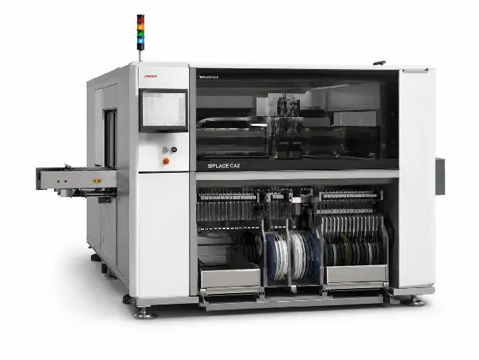
The ASMPT SIPLACE CA2 combines SMT placement and direct die placement from sawn wafers in one machine.
It can place conventional SMD components supplied from tape-and-reel feeders together with bare dies taken directly from wafers. Depending on the installed equipment, the machine supports die attach, flip chip placement, SMD placement or a mixed process using both dies and packaged components.
The CA2 is mainly used for assemblies that contain several component types, such as System in Package products, wafer- and panel-level packages, embedded PCBs and selected power semiconductor products.
ASMPT SIPLACE CA2 Machine Information
| Manufacturer | ASMPT |
|---|---|
| Model | SIPLACE CA2 |
| Machine Type | Chip assembly and SMT placement machine |
| Placement Processes | SMD placement, direct die attach and flip chip placement |
| SMT Placement Speed | Up to 76,000 components per hour |
| Die Attach from Wafer | Up to 54,000 dies per hour |
| Flip Chip from Wafer | Up to 51,000 dies per hour |
| Standard Accuracy | 20 µm at 3 sigma |
| Accuracy Options | 15 µm or 10 µm at 3 sigma |
| Placement Head | SIPLACE CP20 |
| Component Range | 0201 metric to 8.2 × 8.2 × 4 mm |
| Wafer Handling | Multi Wafer System with support for up to 50 different wafers |
| Wafer Change Time | Approximately 13 seconds |
| Feeder Capacity | Up to 80 × 8 mm tape-and-reel feeder positions, depending on configuration |
| Single-Lane Substrate Size | Up to 620 × 700 mm for applicable 20 µm and 15 µm configurations |
| 10 µm Working Area | Up to 300 × 300 mm in single-lane configuration |
| Dual-Lane Substrate Size | Up to 375 × 260 mm in standard dual-lane operation |
| Machine Dimensions | Approximately 2.56 × 2.50 × 1.85 m |
| Cleanroom Classification | Class 7 according to DIN EN ISO 14644-1 |
The maximum SMD, die-attach and flip chip outputs are published platform values. Actual output and accuracy depend on the placement heads, wafer systems, conveyor, component mix, working area and process used on the machine.
Applications
The CA2 is used when a product contains both bare dies and conventional SMD components, or when dies need to be placed directly from the wafer without first converting them to tape-and-reel packaging.
System in Package assembly
Wafer-level packaging
Panel-level packaging
Embedded PCB assembly
Multi-die products
Chip-on-wafer placement
Selected power semiconductor assemblies
Products combining bare dies and packaged SMD components
Direct-wafer processing requires the correct wafer chuck, ejector, die buffer, camera, wafer-map software and pickup tooling. Flip chip applications may also require a dipping unit and process-specific inspection equipment.
Used Machine Configuration and Condition
A used SIPLACE CA2 should be compared by installed equipment rather than by model name alone. Machines may have different wafer systems, feeder capacity, conveyor layouts, cameras, software and inspection options.
The configuration list should identify:
Number and type of CP20 placement heads
Number of installed Multi Wafer Systems
Wafer exchange unit, chucks and supported wafer frames
Die ejectors and die-buffer configuration
Feeder tables and available feeder positions
Single- or dual-lane conveyor
Maximum substrate dimensions for the installed conveyor
Linear Dipping Unit, if installed
Component sensor and die inspection cameras
Die-crack and die-chipping inspection options
On-board PCB inspection, if installed
Wafer mapping and single-die traceability software
JEDEC tray or J-boat handling options
Included feeders, nozzles, chucks, ejectors and product tooling
The machine condition should be stated as as-is, powered on, tested or refurbished. A useful operating check covers machine startup, placement-head movement, wafer loading and exchange, die ejection, feeder communication, camera recognition, conveyor transport and current alarm status.
A dry-cycle video confirms basic movement but does not confirm die pickup, placement accuracy or production readiness. These require suitable wafer material, tooling and a defined test process.
Availability and Price
SIPLACE CA2 machines are supplied according to current new or used equipment availability. The price depends mainly on the number of wafer systems, placement-head configuration, conveyor, inspection options, software, included tooling and machine condition.
| Availability | Check current inventory and lead time |
|---|---|
| Condition | New, used, tested or refurbished according to the machine offered |
| Price | Quoted according to configuration and delivery scope |
| Machine Information | Nameplate, configuration list and photographs provided when available |
| Inspection | Operating video or on-site inspection subject to machine location |
| Export Packing | Available |
| International Delivery | Available subject to destination and export requirements |
For availability and pricing, provide the die and wafer information, SMD component list, substrate dimensions, required placement process, accuracy, production target and destination country.