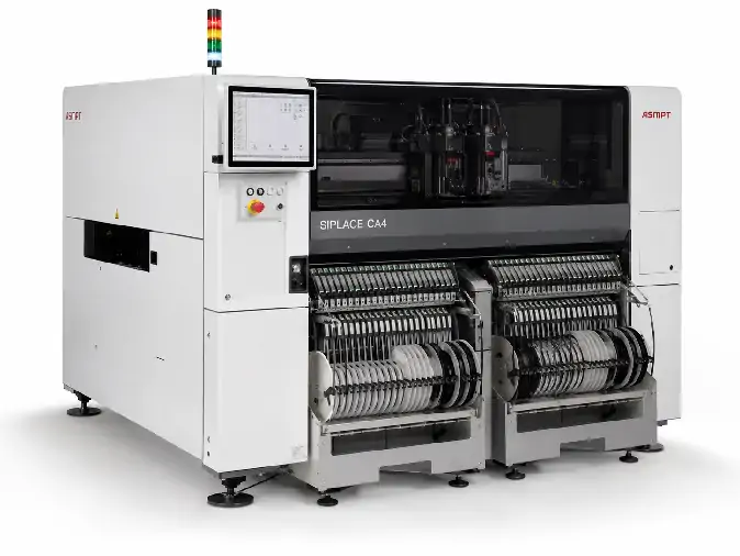
The ASMPT SIPLACE CA4 is a configurable chip assembly machine that can place bare dies directly from wafers as well as conventional SMD components supplied from feeders.
Depending on its configuration, the machine supports die attach, flip chip placement, SMD placement or a combination of these processes. This allows bare dies and packaged components to be assembled on the same substrate without transferring the product between separate placement systems.
The SIPLACE CA4 has four material positions. Each position can be fitted with a SIPLACE Wafer System or a feeder changeover table. The performance and application of a used machine therefore depend on how these four positions and its placement heads are configured.
ASMPT SIPLACE CA4 Specifications
| Manufacturer | ASMPT |
|---|---|
| Model | SIPLACE CA4 |
| Equipment Type | Chip assembly and die placement machine |
| Supported Processes | SMD placement, direct die attach and flip chip placement |
| Material Positions | Four configurable positions for wafer systems or feeder changeover tables |
| SMD Placement Speed | Up to 126,500 components per hour with four feeder changeover tables |
| Flip Chip Placement Speed | Up to 46,000 components per hour with four wafer systems |
| Die Attach Speed | Up to 30,000 components per hour with four wafer systems |
| Placement Accuracy | Up to ±10 µm at 3 sigma for specified wafer-lane applications |
| Panel-Lane Accuracy | Up to ±12 µm at 3 sigma for specified applications |
| SMD Placement Accuracy | Up to ±15 µm at 3 sigma |
| Flip Chip Die Size | 0.5 to 15 mm |
| Die Attach Die Size | 0.8 to 15 mm |
| Minimum Die Thickness | 50 µm for applicable wafer processes |
| Minimum Bump Size | 25 µm |
| Minimum Bump Pitch | 50 µm |
| Wafer Size | 4 to 12 inches |
| Placement Force | Touchless placement or approximately 0.5 to 15 N, depending on the installed head |
| Substrate Thickness | Approximately 0.3 to 4.5 mm, depending on the conveyor |
| Maximum Substrate Range | Up to approximately 685 × 650 mm, depending on the conveyor configuration |
| Machine Dimensions | Approximately 3,778 × 2,100 × 1,835 mm with wafer system |
| Power Supply | 3 × 400 VAC, 50/60 Hz |
The maximum SMD, die-attach and flip chip speeds refer to different material configurations. A single machine should not be assumed to achieve all three maximum figures at the same time.
Material and Process Configuration
The four material positions are the most important part of a SIPLACE CA4 configuration. A position may be equipped with a wafer system for bare dies or a feeder changeover table for tape-and-reel components.
A machine intended mainly for SMD assembly may have more feeder-table positions. A system used for multi-die products may have several wafer systems. Before comparing two machines, confirm the allocation of all four positions.
Number of installed SIPLACE Wafer Systems
Number of feeder changeover tables
Wafer sizes and supported wafer frames
Placement-head types and nozzle configuration
Die attach or flip chip process setup
Installed conveyor type and usable substrate size
Wafer-map and traceability software
Linear dipping unit, if installed
Included feeders, nozzles, ejectors and tooling
The optional linear dipping unit can apply flux or another compatible material before placement. Whether the machine can run a specific flip chip process depends on the dipping equipment, die and bump dimensions, material, substrate and downstream bonding or reflow process.
Typical Applications
Direct placement of bare dies from wafers
Die attach onto PCBs, ceramics or other substrates
Face-down flip chip placement
Mixed bare-die and SMD assembly
System-in-package production
Multi-chip and hybrid electronic assemblies
Assembly on FR4, ceramic, flexible circuits or carriers
The machine is especially relevant when one product contains both wafer-supplied dies and feeder-supplied SMD components. Product suitability should still be confirmed from the actual die, wafer, substrate and required placement process.
View more available die bonders and chip assembly equipment.