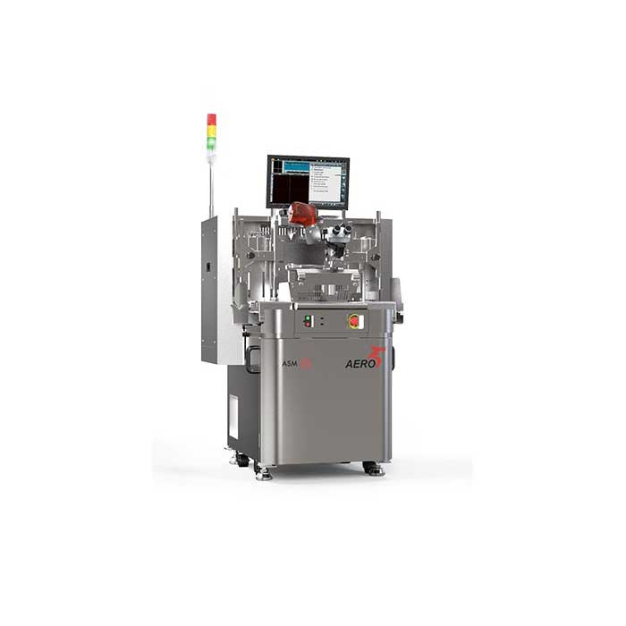
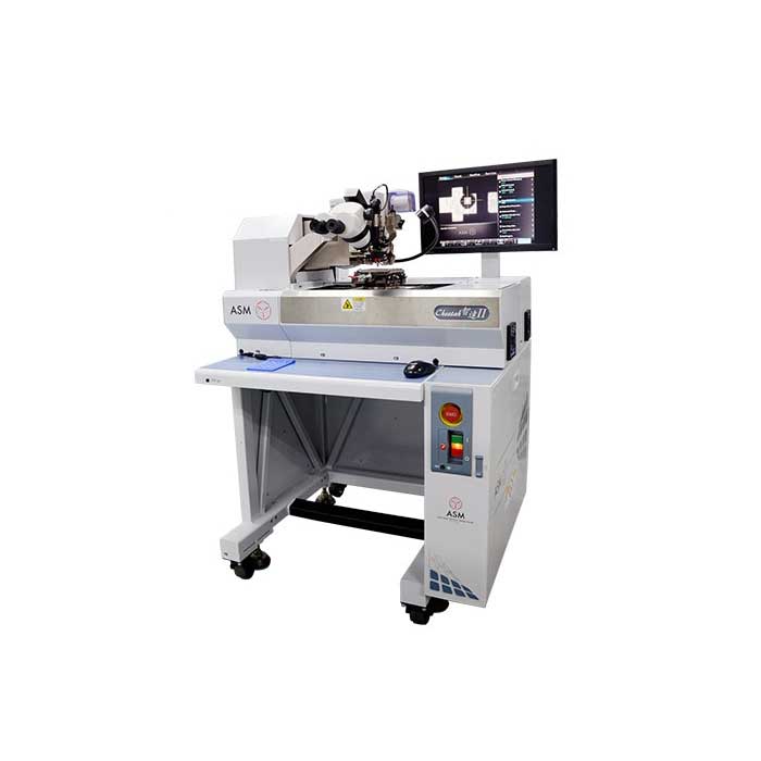
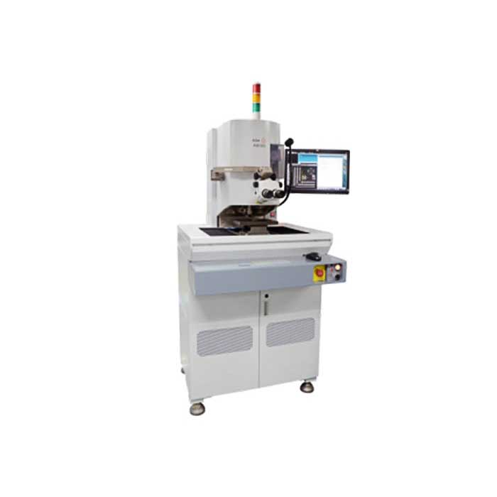
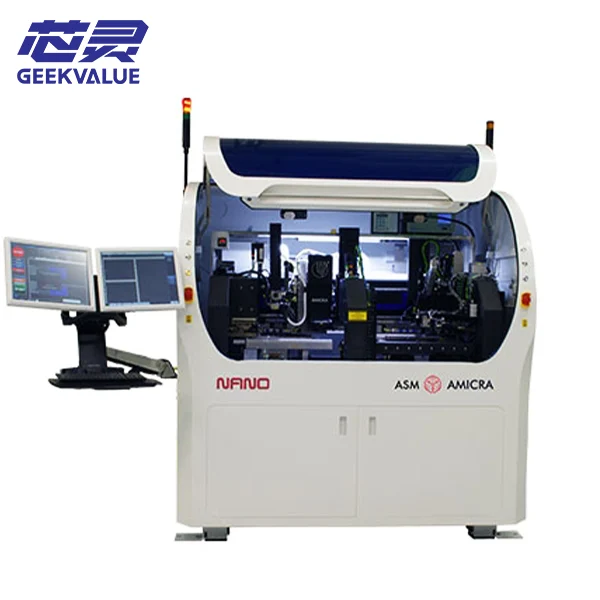
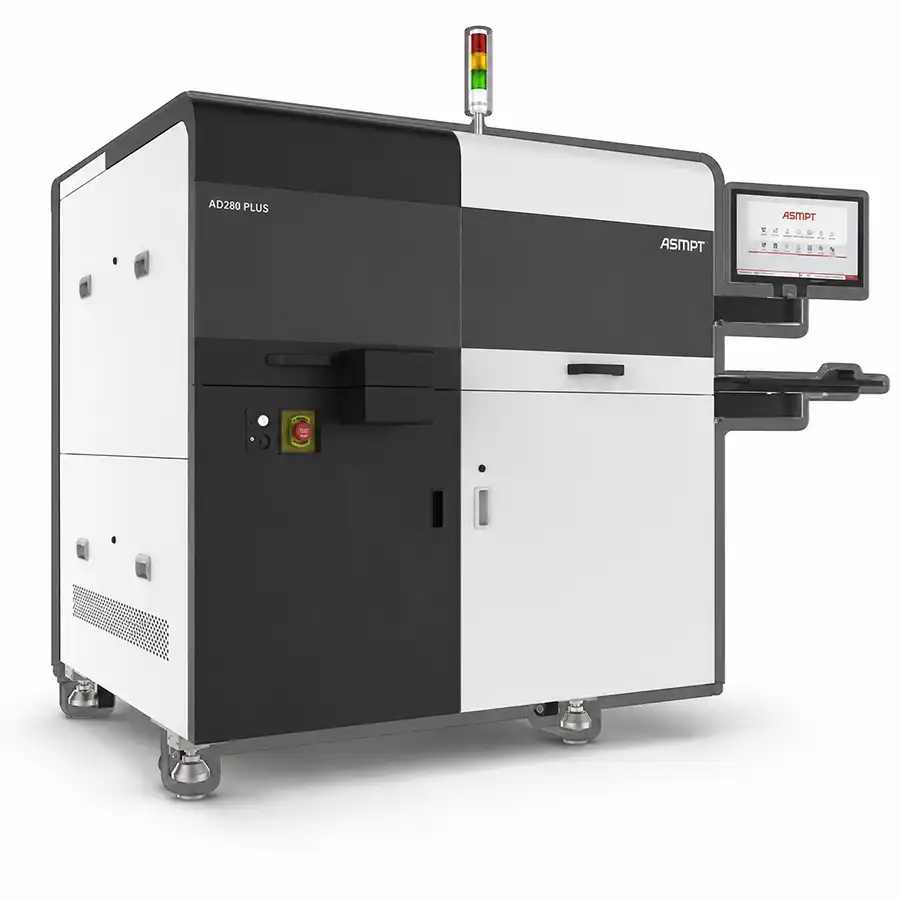
The ASMPT AD280 Plus is an automatic high-precision die bonder with published XY placement accuracy of ±3 μm @ 3σ using look-through pattern recognition.
For a used AD280 Plus, that specification should be treated as a capability to verify rather than a result automatically transferred with the machine. Accuracy depends on the vision system, mechanical condition, calibration, tooling, material and test method.
The most useful evidence is not a startup video or a single successful placement. It is a recorded placement study using representative dies and substrates across a meaningful number of cycles.
What ±3 μm @ 3σ Really Means
The ±3 μm @ 3σ specification is a statistical placement result obtained under defined conditions. It should not be interpreted as a guaranteed maximum error for every die, substrate, process or used machine.
A useful accuracy report should identify:
The die and substrate used for testing
Face-up or flip-chip placement mode
Number of measured placements
Measurement method and measuring equipment
Mean X and Y placement offset
X and Y standard deviation or 3σ result
Die-rotation result when required
Machine warm-up and test duration
Results from different positions across the work area
A machine can show low repeatability variation while still carrying a consistent placement offset. Both centering and variation must therefore be reviewed.
Published Capability and Used-Machine Evidence
| Published Capability | What It Means | What Must Be Verified |
|---|---|---|
| ±3 μm @ 3σ XY placement | High-precision placement under specified conditions | Multi-cycle measurement using representative die and substrate material |
| Look-through pattern recognition | Patented optical alignment technology | Cameras, lenses, lighting, optical cleanliness, calibration and recognition stability |
| Flip-chip handling | The platform can support flipped-die placement | Installed flip mechanism, optics, software, bond tools and product-specific alignment |
| Wafer input | Wafer on expander or clamp ring is the standard input format | Wafer diameter, frame type, expander, ejector and wafer-map compatibility |
| Alternative die inputs | Waffle pack, Gel-Pak, tray and tape feeder are available configurations | Confirm which physical handlers and software functions are installed |
| Material traceability | Barcode, 2D code or OCR can be used on substrate, wafer or die | Reader hardware, camera, software license, code format and factory-system interface |
| Machine dimensions | Approximately 2,150 × 1,400 × 2,300 mm | Confirm the actual unit, auxiliary modules, service clearance and shipping fixtures |
When a Used AD280 Plus Makes Sense
The AD280 Plus is easier to justify when the product genuinely needs approximately ±3 μm placement and the available machine contains the required material-handling and process options.
Die or optical-component placement with tight XY tolerance
Flip-chip placement using compatible dies and substrates
Products requiring alignment through look-through pattern recognition
Multiple die-input formats when the corresponding handlers are installed
UV adhesive processes when curing hardware is installed
Products requiring controlled bond force when the sensor option is installed
Traceability projects using compatible barcode, 2D-code or OCR functions
It may be an unnecessarily expensive or complex choice when the product only requires conventional leadframe die attach at a much wider placement tolerance.
For high-volume 12-inch wafer-to-leadframe epoxy production, the ASMPT AD8312Plus may be a more relevant platform. If the priority is rapid repetitive placement of small dies rather than several-micron alignment, the ASM AD50Pro should be evaluated separately.
Look-Through Optics Are Central to the Machine’s Value
The AD280 Plus should not be evaluated only as a mechanical pick-and-place system. Its high-precision positioning depends heavily on the complete optical chain.
The inspection should cover:
Upper and lower cameras
Lenses and look-through optical components
Lighting channels and intensity stability
Optical contamination, scratches or haze
Camera mounting and mechanical stability
Pattern-recognition software and licenses
Calibration plates, targets and procedures
Recognition performance on the intended die and substrate
A clear camera image is not sufficient evidence. The system must repeatedly calculate and correct the relative die-to-substrate position during actual placement.
Flip-Chip Capability Must Be Demonstrated Separately
ASMPT identifies flip-chip handling as a platform capability, but this does not mean every used AD280 Plus is ready for every flip-chip product.
The available machine should be checked for:
Installed die-flipping mechanism
Die-side and substrate-side recognition
Compatible bond head and collet
Bump or pad visibility under the installed lighting
Substrate fixture and planarity
Parallelism and placement-height setup
Bond-force requirements
Installed adhesive, flux or curing components when required
A face-up placement test does not prove flip-chip capability. The flipped die must be aligned and placed onto representative substrate features.
Optional Functions Must Not Be Presented as Standard
| Option | Why It Matters | Evidence Required |
|---|---|---|
| Bond-force sensor | Provides controlled and monitored placement force | Sensor hardware, controller support, calibration and force-response test |
| Snap UV curing | Supports spot or panel UV curing for compatible adhesives | UV source, optics, power measurement, exposure control and safety interlocks |
| Waffle-pack input | Allows dies to be supplied outside a wafer frame | Handler, tray format, pickup coordinates and software support |
| Gel-Pak input | Supports compatible Gel-Pak die presentation | Installed holder, pickup setup and supported Gel-Pak dimensions |
| Tray or tape feeder | Adds alternative component-input formats | Physical feeder, interface, indexing and software configuration |
| Barcode, 2D code or OCR | Supports material and product traceability | Reader hardware, recognition test, software license and data export |
If an option is physically installed but cannot be calibrated or operated, it should be listed as untested rather than included as a confirmed machine capability.
How to Verify High-Precision Placement
A practical acceptance test should run after the machine reaches a stable operating condition. Representative dies and substrates should be placed at multiple positions rather than repeatedly using only the center of the work area.
Confirm machine leveling, environmental conditions and calibration status.
Load the intended or technically comparable die and substrate.
Use the required face-up or flip-chip configuration.
Run sufficient consecutive placements to produce meaningful measurement data.
Measure X position, Y position and rotation using calibrated equipment.
Review mean offset, variation and results across different work-area positions.
Repeat after sustained operation to identify thermal drift.
Record rejected placements, recognition failures and operator intervention.
The published ±3 μm figure should only be repeated as an actual machine result when the test conditions and measurement report support it.
Information Required for the Available AD280 Plus
| Machine Identity | Model, nameplate, serial number and manufacturing year |
|---|---|
| Previous Application | Original die, substrate and bonding process when available |
| Vision System | Cameras, lenses, lighting, look-through optics and calibration accessories |
| Material Input | Wafer, Waffle Pack, Gel-Pak, tray or tape-feeder configuration |
| Bond Head | Head type, collets, force sensor and associated tooling |
| Flip-Chip Setup | Flip mechanism, recognition functions, tools and completed testing |
| UV Curing | Spot or panel curing hardware, UV source condition and controls |
| Traceability | Barcode, 2D-code or OCR hardware and enabled software |
| Software | Version, licenses, machine backup and available process programs |
| Test Evidence | Power-on, functional, process and measured placement results stated separately |
Used ASMPT AD280 Plus Availability
Price and suitability depend heavily on the installed optics, material handlers, flip-chip hardware, bond-force sensor, UV curing, traceability functions, tooling and completed accuracy test.
Availability: Confirm against the physical machine
Condition: State whether it is as-is, function-tested or process-tested
Configuration: Provide an itemized list of standard and optional modules
Accuracy: Supply measured results when representative testing is available
Price: Quote according to the actual configuration and test scope
Export: International packing and shipment can be arranged
Send the die dimensions, substrate drawing, required placement accuracy, material-input format, face-up or flip-chip process, bond-force requirement, UV-curing requirement and destination through our equipment inquiry form.