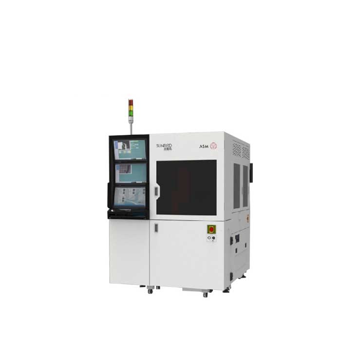
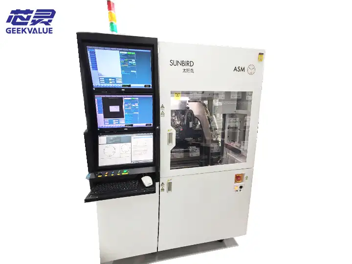
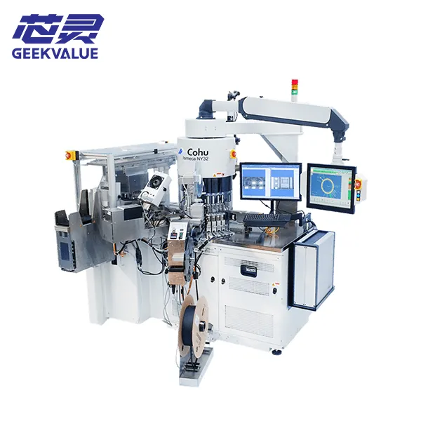
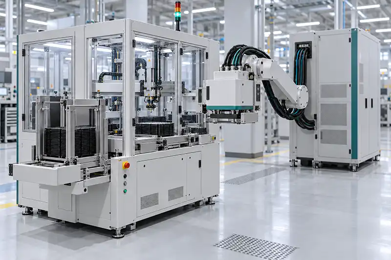
A semiconductor test handler moves devices through the handling sequence, presents them to the test interface and sorts them according to test results. Depending on its configuration, it may also condition devices to the required temperature.
The ATE performs the electrical measurements. The handler and tester must work with the contact hardware, software and material flow as one test cell.
For a used machine, a package-family name or platform specification is only an initial screening point. The installed configuration determines what the individual machine can support.
Begin With a Package Drawing and the Intended Test
Before comparing machines, define the device.
Package labels such as QFN, BGA and SOIC cover different dimensions and constructions. They do not establish whether an installed track, nest, nozzle or contact arrangement will fit.
Prepare a requirement sheet:
| Requirement | Details to provide |
|---|---|
| Device | Package drawing, dimensions, thickness and handling restrictions |
| Input and output | Tray, tube, tape, strip, frame or another format |
| Tester | ATE platform and test-head configuration |
| Parallel test | Required active sites and contact layout |
| Temperature | Required conditions and relevant device power dissipation |
| Production | Test time, output target and product mix |
| Data | Bin mapping, traceability and factory-interface requirements |
| Installation | Floor space, utilities and access restrictions |
These details help narrow the available semiconductor test handler options before time is spent reviewing unsuitable machines.
Identify What the Handler Actually Does
Handler descriptions can overlap with inspection, sorting and finishing equipment.
Some configurations may combine handling with vision, marking or other operations. Those modules do not automatically establish compatibility with the buyer’s intended electrical test.
Ask for a station-by-station description:
How devices enter.
How they are oriented and transported.
Where contact and electrical testing occur.
Which inspection or finishing operations are installed.
How results control sorting.
How devices leave the machine.
For a turret platform such as the ASM Sunbird X8, review the installed station arrangement rather than assuming every machine has the same functions.
Separate Platform Capability From Installed Capability
A platform brochure may describe several package formats, output options or process modules. An individual used machine may include only part of that range.
Record whether each required function is:
Installed and demonstrated.
Installed but untested.
Available through conversion.
Unavailable or unresolved.
A proposed conversion should have its own scope, parts list, cost and delivery estimate. Do not treat possible future capability as an included machine function.
Verify the Change Kit Against the Actual Device
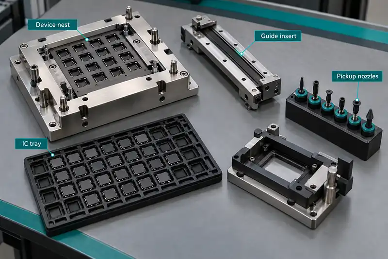
A change kit may include package-specific tracks, nests, nozzles, guides or other handling parts.
Compatibility should be checked against the package drawing and the intended input/output media. A shared package-family name is not enough.
Inspect wear, damage, identification and completeness. Where spare sets are included, list them individually.
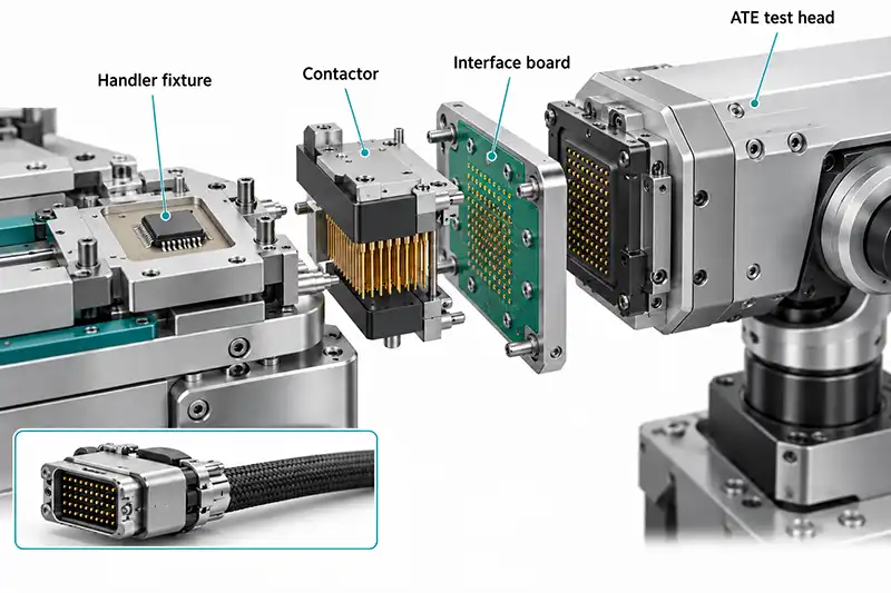
Also distinguish handling parts from the electrical contact system. A machine may have the correct handling kit while still requiring a different contactor or interface assembly.
Confirm the Complete ATE Interface
A statement that a handler supports a tester brand leaves several questions unanswered.
The ATE system, handler, contact hardware and interface software must support the intended combination.
Mechanical connection
Review docking direction, alignment, height, test-head support and clearance.
Where the arrangement uses cables or a different interface structure, document that configuration rather than assuming direct docking.
Contact hardware
Identify the contactor, socket or other relevant contact assembly. Confirm ownership, supply responsibility, site layout and maintenance requirements.
Electrical coordination
Verify the supported handshake, test-start and completion sequence, bin results and fault behavior.
Factory integration
Check lot information, traceability, recipe control and equipment-status requirements separately.
Factory communication support does not establish tester-interface compatibility.
Temperature Capability Needs More Than a Setpoint
Where temperature testing is required, establish how the offered configuration conditions the device and maintains the relevant thermal condition.
A displayed temperature does not independently describe device temperature during electrical testing.
Review:
Measurement location and method.
Conditioning time.
Uniformity across active sites where relevant.
Device self-heating.
Recovery between cycles.
Cooling and utility requirements.
Condensation-control arrangements for cold operation.
A handler sold without the relevant thermal equipment should not be assumed to support it through a software setting.
If the intended process does not require thermal conditioning, confirm that the selected configuration meets the ambient operating requirement without adding unnecessary equipment.
Ask for Throughput Under Identified Conditions
Mechanical handling rate is different from production output.
Actual performance depends on test time, active sites, indexing, loading, conditioning, sorting and interruptions.
A useful demonstration records:
| Record | Purpose |
|---|---|
| Device and package | Identifies the handling task |
| Input/output media | Establishes the material flow |
| Test program and test time | Defines the electrical workload |
| Active sites | Identifies the demonstrated parallel configuration |
| Temperature condition | Explains conditioning requirements |
| Run duration | Defines the extent of the test |
| Alarms and interruptions | Makes lost operating time visible |
| Retests and handling rejects | Helps interpret processed quantities |
| Final output | Distinguishes processed devices from accepted output |
Avoid extrapolating production capability from a brief empty cycle.
A demonstration without the intended ATE or program may still verify useful mechanical functions, but those limits should be stated.
Observe Fault Recovery as Well as Normal Operation
A normal run does not reveal every operational problem.
Include agreed checks for missing devices, blocked tracks, contact problems, full bins and communication interruptions where practical.
Observe whether the system stops correctly, preserves device identity and resumes without creating sorting uncertainty.
Record how interrupted devices are handled. An unclear recovery sequence can matter as much as a short interruption.
Inspect the Individual Machine
Review the machine identity, maintenance records, motion systems, pneumatics, sensors, controller and installed modules.
Pay attention to areas connected to the intended handling process. Inspect the condition of package-specific components and check whether supplied parts match the configuration record.
Product pages such as the Cohu Ismeca NY32 can help identify a candidate platform. The purchase still needs evidence from the specific unit offered.
Software and Recovery Information Belong in the Purchase
Confirm the software version, licensing requirements, configuration files and available backups.
Identify dependencies involving control hardware, vision systems and communication interfaces. Establish what is needed to restore the machine after controller or storage failure.
The delivery record should distinguish supplied documentation from information that is unavailable.
Where recovery has not been demonstrated, keep that limitation visible.
Define Factory and Site Acceptance
If the buyer’s tester is unavailable before shipment, complete the agreed subsystem checks and document the remaining integration work.
Separate responsibilities clearly:
| Stage | Scope to agree |
|---|---|
| Before shipment | Identity, configuration, mechanical functions and available integrated tests |
| Installation | Positioning, utilities, assembly and connection |
| Site acceptance | Buyer’s ATE, intended device, contact hardware and software |
| Production qualification | Required output, quality and operating conditions |
| Open items | Responsible party, evidence required and completion conditions |
The quotation should list the handler, change kits, docking or interface hardware, contact components, thermal equipment, software, spares and documentation.
When we review a used-handler enquiry, the package drawing and ATE information are the most useful starting documents. They allow configuration gaps to be discussed before a machine is selected.
Frequently Asked Questions
Does support for QFN or BGA prove compatibility?
No. Dimensions, handling details, installed tooling and contact requirements still need verification.
Can a handler be moved between different ATE platforms?
Possibly, but the mechanical interface, contact hardware, communication and software must be evaluated. Conversion should not be assumed.
Does increasing site count always increase output?
No. The tester, program, contact system and device must support the intended parallel configuration.
Is a dry-cycle video enough for acceptance?
It can demonstrate visible mechanical functions. It does not establish electrical integration, thermal performance or production output.
What if a complete integrated test is unavailable?
Agree on subsystem tests, identify unverified functions and define the remaining site-acceptance responsibilities before shipment.
What information should I send for a quotation?
Provide the package drawing, input/output media, ATE platform, interface details, active-site requirement, temperature conditions, production target, destination and required delivery scope.