Laser Source Module
Source housing, emission behavior, module condition and reported output changes.
Semiconductor Equipment Repair
Repair support for no laser output, low power or unstable emission.
We separate source, driver, control and thermal-path faults before defining a repair scope. Serviceable electronic sections are repaired; sealed gas tubes or pump diodes beyond usable output are routed to matched replacement.
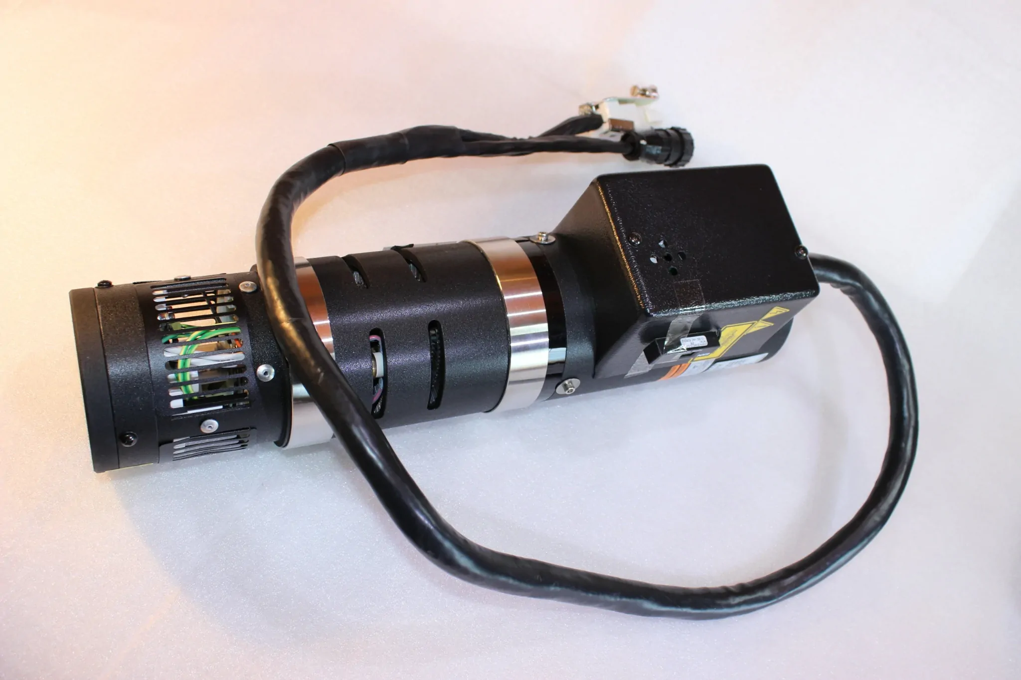
01 / Service coverage
The repairable section depends on source design, part number and component condition. We review the laser assembly together with its supporting electronics and interfaces, rather than assuming every no-output fault means the complete source has failed.
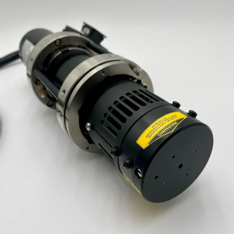
Source housing, emission behavior, module condition and reported output changes.
Related driver electronics, power input sections and control response.
Accessible control, feedback and interface electronics associated with source operation.
Relevant temperature monitoring, cooling and interlock / protection circuits.
Output connectors, fiber delivery and optical subassemblies can be inspected where applicable; repair or replacement depends on the interface design and available parts. Final coverage is confirmed against the exact unit before work begins.
02 / Customer symptoms
The symptom is the starting point for fault isolation. A source alarm, low reading or missing beam may come from the laser assembly, its drive electronics or a supporting condition.
The source does not emit, or the tool cannot complete its laser start sequence.
Measured output drops below the expected operating level or declines over time.
Output fluctuates, drifts or becomes intermittent during equipment operation.
The source trips during startup or reports a fault associated with drive, cooling or protection conditions.
03 / Repair value
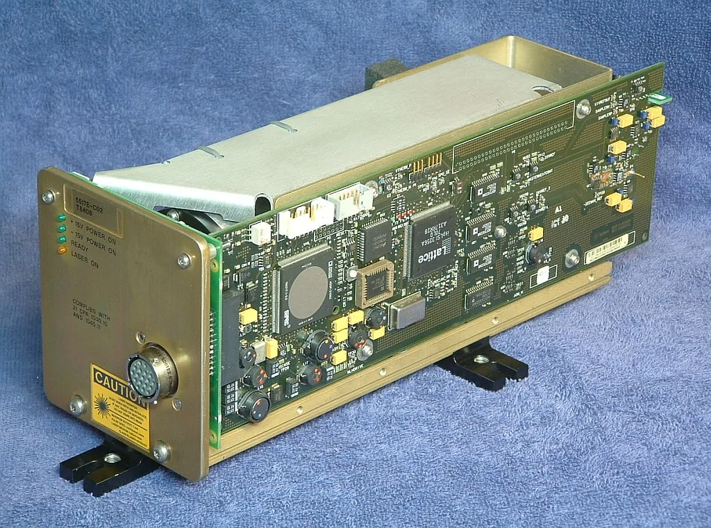
A complete laser source replacement may not be necessary when the failure is isolated to a serviceable supporting section. Our assessment focuses on identifying the affected assembly and defining a practical recovery route.
Separate source, driver, power and control symptoms before deciding what needs attention.
Consider repair of a serviceable electronic section instead of defaulting to complete source replacement.
Compare repair, overhaul and matched replacement when parts or source condition limit recovery.
Define checks around the source type and available test configuration — including output power, stability and interface response where applicable; bench results are kept separate from tool qualification.
04 / Recovery decision
The right route depends on the failed section, source condition, parts availability and whether the required function can be checked after service.
Address a serviceable fault in a driver, power or control section without replacing the complete source assembly.
Consider when the failure is isolated and the remaining assembly is serviceable.Assess a broader restoration when multiple related sections or operating conditions have degraded together.
Subject to source design, component availability and suitable verification.Review a compatible replacement when critical parts are unavailable or repair is not practical.
Match by part number, revision, output characteristics and tool interface. Sealed gas-tube depletion and pump-diode degradation beyond usable output are routed to replacement rather than repair.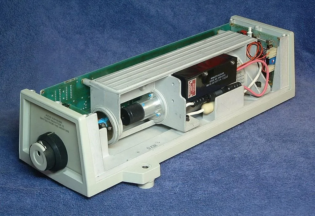
05 / Fault handling examples
These representative assessment paths show how a laser fault can be separated into source, electronics and operating-condition checks. They are not named GK-SEMI customer cases or claims of measured repair results.
The tool reports a source fault during startup, but the laser assembly may not be the only failure point.
Output changes during operation. The source, control electronics, thermal conditions and output interface need to be considered together.
Questions before sending
Practical answers for engineers and procurement teams evaluating laser source repair.
Depending on the unit, the review may cover the source assembly, driver and power electronics, control/interface PCB, and related cooling or protection circuits. The exact repair scope is confirmed from the part number and module design.
He-Ne/interferometer, argon-ion, DPSS/UV and laser-diode source families are useful starting categories for identification. Model-level support is not universal; send the nameplate and equipment application for confirmation.
No. Power input, driver response, enable signals, interlocks, cooling and tool-side control conditions can also prevent emission. The start sequence and alarm history help narrow the failure point.
Potentially. The cause may be within the source, supporting electronics or output interface. Repair feasibility depends on the source construction, component condition and whether the relevant function can be checked.
Related electronic sections can be assessed when they are identifiable and accessible as a serviceable assembly. Share the board or unit part number and photographs so the exact scope can be reviewed.
Any frequency, lock or stability verification depends on the specific laser design and availability of suitable measurement equipment. A general output check should not be treated as equivalent to interferometer qualification.
Where practical, a compatible replacement or alternative sourcing route can be reviewed. Matching must consider the part number, revision, output characteristics, interface and installed tool configuration.
Send the laser source manufacturer and part number, equipment model, nameplate photos, alarm code or fault history, output symptoms, and any available driver, power or cooling information.
Engineering inquiry
Send the part number and fault behavior. We can review the source identity, identify the information needed for assessment and clarify a practical repair or replacement route.