Semiconductor Equipment Optical Modules

Optical Module Repair

Repair support for imaging, alignment and optical detection functions on semiconductor equipment.

For semiconductor equipment, we separate module-level optical, mechanical and electronic faults from machine-side conditions before agreeing a scope. Serviceable assemblies are repaired; sealed or compromised optics go to matched replacement.

Send the equipment model, module part number and observed fault for an initial review.

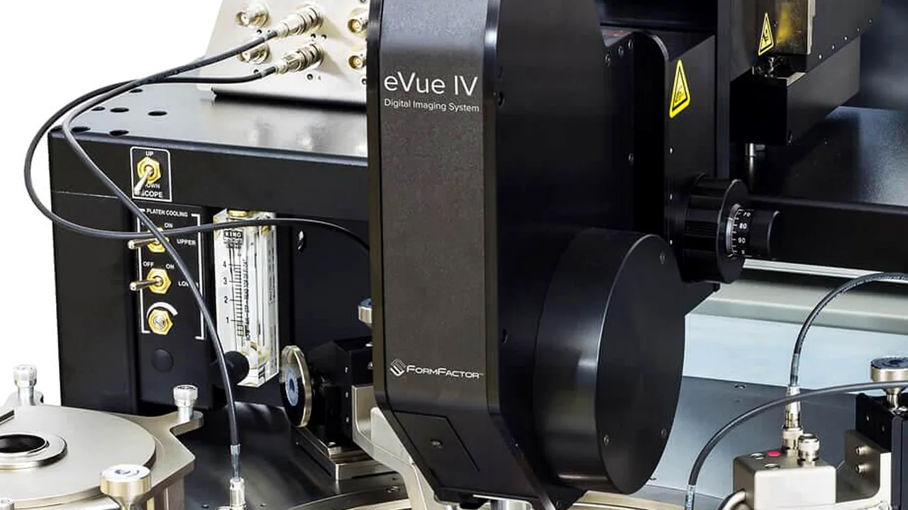
FormFactor eVue IV digital imaging system integrated on a semiconductor wafer probing platform
Imaging & AlignmentCamera and imaging assemblies
Optical DetectionDetector and receiver modules
Optical Path AssembliesServiceable lenses and optics
Module-Level AssessmentRepair scope and return checks

01 / Repair coverage

Optical Modules in Scope

Our review focuses on three assembly groups used around semiconductor imaging, wafer alignment, inspection and optical detection. Exact coverage is confirmed against the module identity and condition.

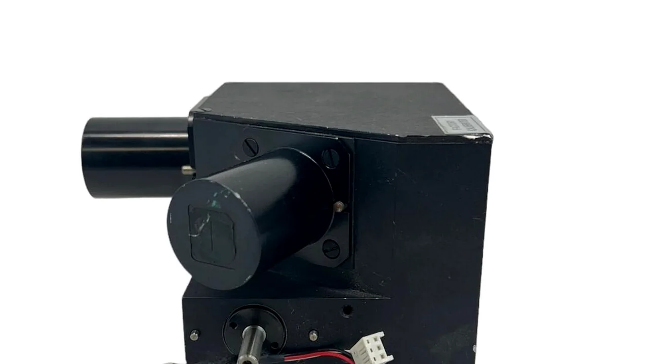
Standalone semiconductor alignment camera module with lens housing, rotary shaft and cable lead on a neutral background
01 / IMAGING & ALIGNMENT

Alignment Cameras & Imaging Heads

Assessment of alignment camera modules, lens assemblies, and image sensor electronics. We separate camera-level failures (such as focus drift or sensor degradation) from machine-side errors caused by stage movement, encoder feedback, or reference positioning.
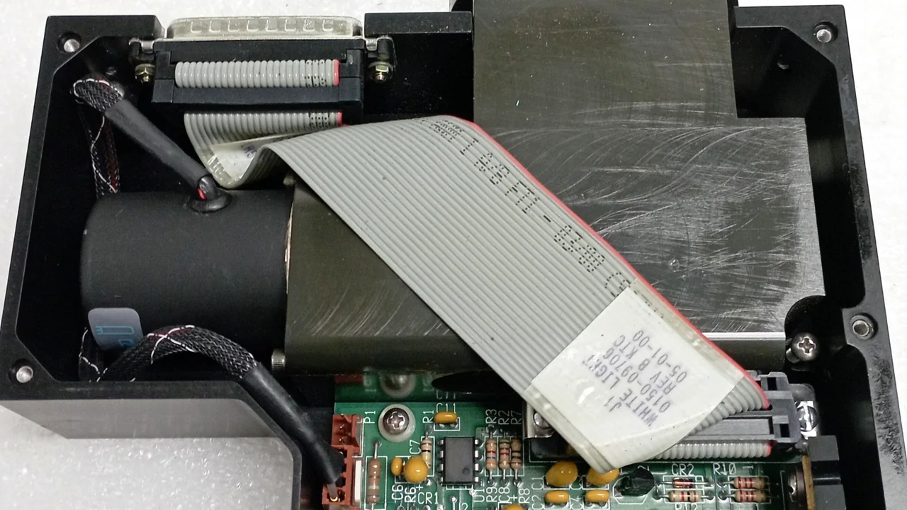
Opened optical detection module showing monochromator interconnect electronics, ribbon cable and optical housing
02 / DETECTION & SPECTROSCOPY

Monochromators & Endpoint Detectors

Repair of optical detection assemblies, including OES endpoint detectors and monochromator units used on platforms such as AMAT and Lam Research. Evaluation covers PMT degradation, grating alignment, and internal signal board faults.

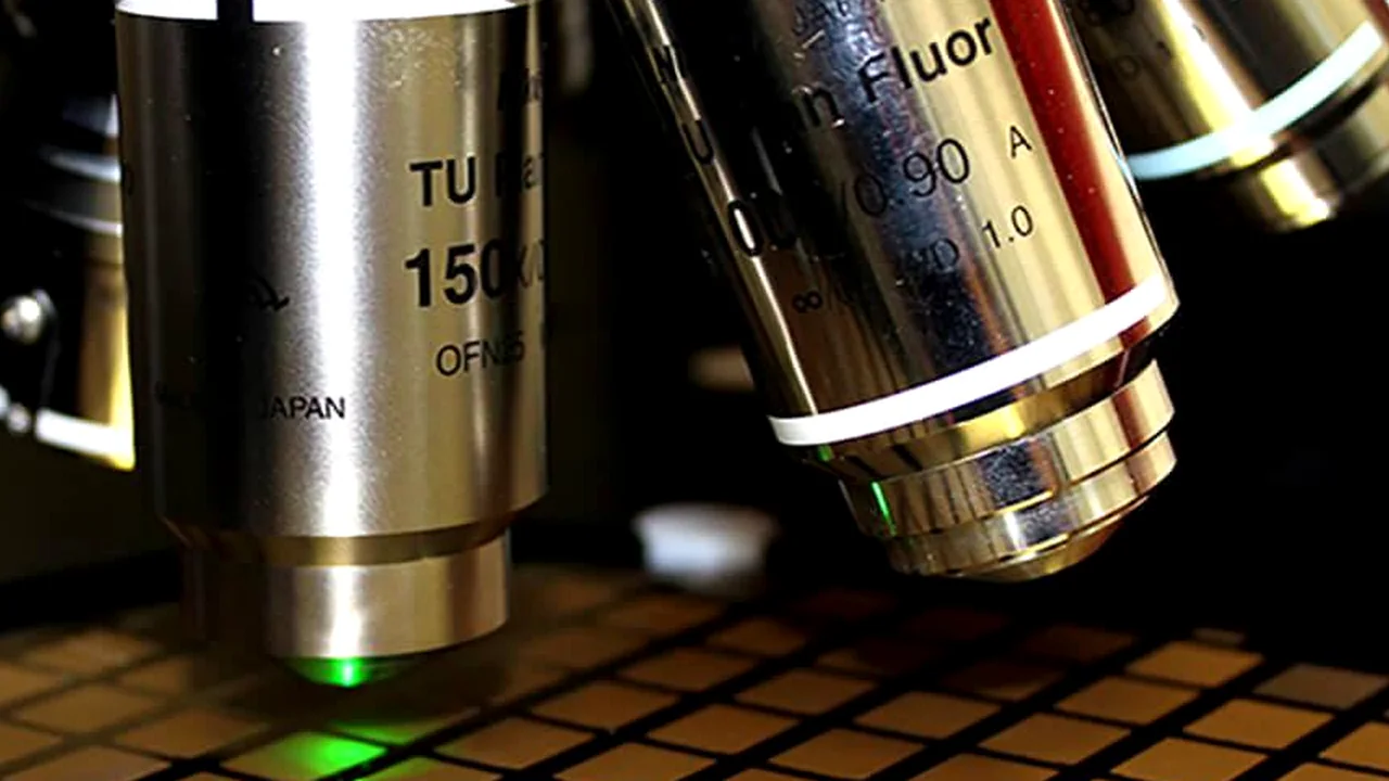
Microscope objective lenses positioned over a semiconductor wafer for optical inspection and imaging
03 / OPTICAL PATH & COMPONENTS

Lenses, Filters & Fiber Coupling

Inspection and service of accessible optical path components, including objective lenses, filters, mirrors, and fiber-optic interfaces. Work includes gentle cleaning, mechanical re-mounting, and alignment checks where the module design permits.

Service boundary: This service focuses on optical modules and serviceable optical assemblies. Encoder readheads and scales are handled separately under Encoder Repair; standalone laser sources belong to the Laser Source Repair category. Final on-tool image registration or process qualification is agreed separately. Brand names are used for identification only and do not imply OEM authorization.

02 / Recovery options

Repair, Overhaul or Replace?

The practical route depends on the failed assembly, optical condition, module construction, available parts and compatibility with the installed tool.

Route A / Localized fault

Repair the Original Module

When the fault is isolated to a serviceable component, connector, mounting point or module interface, focus work on the affected area and retain the original assembly where practical.

Useful when the core optical assembly and installed configuration remain serviceable.
Route B / Extensive damage

Overhaul the Assembly

When several serviceable elements show degradation, review a broader scope covering inspection, approved cleaning, component replacement and optical or mechanical adjustment where applicable.

Subject to coating, material, access and assembly design.
Route C / Beyond repair

Find a Compatible Replacement

If sealed optics, structural damage or unavailable critical components prevent a dependable repair, assess a replacement against the installed module and tool configuration.

Match part number, revision, optical function, mounting and interface—not appearance alone.

03 / Repair value

Our Repair Approach

01 / FAULT ISOLATION

Separate Module from Tool Faults

Distinguish optical, mechanical and electrical issues within the assembly from stage movement, encoder feedback, external wiring or machine-side reference errors.

02 / ORIGINAL CONFIGURATION

Assess Repair Before Replacement

Review the original module, revision and serviceable components before choosing a replacement route, helping avoid an unnecessary change to the installed configuration.

03 / AGREED VERIFICATION

Define the Return Checks

Set practical optical, signal and interface checks around the module function and available setup, with any remaining machine-side work clearly identified.

04 / COMPONENT EXPERTISE

Sensor & Board-Level Repair

Capability extends to specific optical components, including CCD/CMOS sensor electronics, PMT degradation, and monochromator interconnect board failures, with applicable signal and interface checks defined before return.

04 / Service workflow

From Module Review to Return

The repair route is defined around the module's optical function, construction and reported failure—rather than a fixed calibration sequence.

01

Identify the Module

Confirm the equipment, part number, revision, installed function and fault evidence supplied with the inquiry.

02

Isolate the Fault Path

Review accessible optics, mounting references, detector or camera response, electrical connections and relevant interfaces.

03

Agree the Repair Scope

Confirm repairable components and any cleaning, replacement or adjustment work appropriate to the assembly design.

04

Check and Document

Complete applicable module-level function, optical or signal checks and record any remaining tool-side verification required.

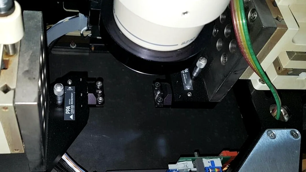
Installed semiconductor optical module under a microscope assembly with cabling and positioning fixtures

Verification boundary: Checks depend on module design and available reference setup. Bench-level results do not replace final image registration, focus calibration, system alignment or process qualification on the installed tool unless separately included in the agreed scope.

05 / Application examples

Representative Repair Scenarios

These examples show how an optical-module inquiry can be assessed. They are representative service scenarios, not named customer cases or measured repair results.

Scenario A / Imaging & alignment

Alignment Camera Image Drift & Loss

Reported Symptoms: Blurred images, inconsistent focus, or image drift during repeated alignment cycles, resulting in wafer alignment failures.

Diagnostic Split: Isolate module-level faults (sensor degradation, focus mechanism binding, shielding issues) from machine-side errors (stage backlash, lighting decay, encoder drift). A known-good camera or reference target is used to separate module-level drift from stage or illumination contributions before opening the assembly.

Scenario B / Optical detection

OES Endpoint Signal Degradation

Reported Symptoms: Weak spectrum signals, high noise levels, or intermittent endpoint detection during plasma processing, leading to over-etching or false alarms.

Diagnostic Split: Review PMT (photomultiplier tube) aging, grating condition, and fiber optic end-face integrity. Scope is confirmed by exact unit identity (e.g., AMAT, Lam OES) to check spectral compatibility.

Repair Boundary: Fiber end-face contamination is assessed for cleaning; PMT degradation beyond usable signal-to-noise and grating efficiency loss that cannot be restored by alignment are routed to replacement assessment.

Scenario descriptions are for service explanation only. They do not represent a specific customer, OEM model, guaranteed repair outcome or confirmed test result.

06 / Questions before sending

Optical Module Repair FAQ

What types of optical modules can be assessed?

The review focuses on imaging and alignment modules, optical detection assemblies and serviceable optical-path components used in semiconductor equipment. Exact coverage depends on the part number, module construction and condition.

Do you support alignment camera repair?

Alignment camera assemblies and their serviceable optical, mounting and interface components can be reviewed. The assessment distinguishes camera-module faults from stage movement, encoder feedback and machine-side reference issues.

Can you assess a monochromator or optical endpoint detector?

These are specific optical detection assemblies. Send the equipment model, unit part number and revision so the applicable module family and repair scope can be checked before confirming coverage.

Does an out-of-focus image always mean the camera has failed?

No. Focus setting, optical contamination, mounting movement, sensor response, cable connections and machine references can all affect the image. The module should be isolated from the surrounding system before replacement is recommended.

Can lenses, filters or mirrors be cleaned or realigned?

Some accessible optical components may be serviceable. The method depends on coating, material, contamination, damage and assembly design; sealed or sensitive optics are not assumed to be cleanable or restorable.

What can be checked after optical module repair?

Where the module and available setup permit, checks may cover image or detector response, optical output, signal stability, relevant interfaces and accessible mechanical references. Final on-tool calibration is a separate scope unless agreed.

Can obsolete optical modules be repaired or replaced?

The original unit can be assessed for repair feasibility. If replacement is more practical, matching should consider part number, revision, optical function, mounting, connectors and the installed tool configuration.

What information should I send for an assessment?

Send the equipment model, module part number and revision, installed function, fault description or alarm, clear photos of the label and connectors, and any available image or signal results.

Engineering inquiry

Send Your Module Details

Share the equipment model, module part number, revision, and observed fault or alarm. A clear description helps us identify the assembly and review the next practical step. No online form required.

Request a Repair Assessment