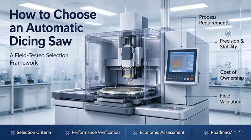
An automatic dicing saw sits at the end of a long chain of process decisions, and it is usually the last place where a yield problem can be caught before the wafer leaves the line. When a package fails electrical test, or when a thin die cracks during die attach, the dicing step is often the first suspect. A dicing saw therefore deserves more scrutiny than a simple price comparison.
Matching Dicing Saw Specifications to Your Workpiece
Every specification conversation should begin with the parts you need to cut. A dicing saw's working envelope is fixed at the factory, and no amount of process tuning will make a 200 mm chuck accept a 300 mm wafer.
Round wafers and square panels are not interchangeable. Much of the equipment on the market is designed around circular semiconductor wafers, but packaging lines increasingly run QFN and BGA lead frames, PCB panels, and glass substrates that are square or rectangular. Some dicing saw models handle both. ADT's 7232, for example, accepts 12-inch round workpieces or square parts up to 253 by 243 mm when mounted on a frame, while the 8030 offers a 12 by 12 inch square chuck alongside its 12-inch round capability. A good share of changeover problems trace back to a chuck geometry that was specified for today's product rather than the panel format a customer adopted eighteen months later.
Wafer size transitions deserve early attention. If there is any chance your line will move from 200 mm to 300 mm within the life of the equipment, confirm that the dicing saw handles both cassette formats. The DFD6363 supports standard dicing cassettes and FOUPs in both Φ200 mm and Φ300 mm sizes. Buying an 8-inch-only saw today often means buying again in two years.
Thickness is the constraint that catches people off guard. A dicing saw configured for 700 μm silicon behaves very differently when asked to handle a 50 μm thinned wafer, where handling forces and breakage risk dominate. At the other extreme, silicon carbide power substrates demand far more spindle torque than silicon. Laser tools have carved out a niche here. The process developed by LIDROTEC and TRUMPF cuts wafers of varying thickness and material at roughly three times the speed of a mechanical saw, and ASMPT's ALSI LASER1206 covers grooving from 60 to 800 μm and cutting from 20 to 200 μm — a range that spans both ultra-thin logic wafers and thicker power devices.
Size the chuck to the largest part you will ever run, not the average part you run today. An undersized chuck is one of the most common bottlenecks we see on an automatic dicing saw, and one of the most expensive to fix after installation.
How Spindle Configuration Affects Dicing Saw Performance
On any automatic dicing saw, the spindle is where the cutting actually happens, and its configuration determines what processes are possible, not just how fast they run.
A dual-spindle dicing saw carries two opposing spindles that can cut simultaneously, or one can cut while the other dresses or grooves. ADT's 8030 uses two 1.8 kW or 2.2 kW opposed spindles rated to 60,000 rpm. The appeal is obvious for products that need multiple passes or two blade specifications: one setup completes more work, and the wafer is handled fewer times, which matters when breakage risk is real. But dual-spindle tools cost more, occupy more floor space, and introduce a second spindle to maintain. A line that runs simple full-cut operations on a single material may never recover that premium.
Power and speed need to be matched to the hardest material in the mix, not the most common one. Cutting silicon is a different proposition from cutting sapphire or silicon carbide ceramics, where torque demand rises sharply. A 2.2 kW spindle holds speed more consistently under that load. Speed range matters too: 60,000 rpm covers most blade work, but ultra-thin blades and specialty processes sometimes benefit from the 80,000 rpm ceiling found on high-speed spindle options such as those offered for the DFD6363, which pairs a 1.8 kW spindle at 6,000–60,000 rpm with a high-speed alternative at 20,000–80,000 rpm.
Some suppliers distinguish standard, high-speed, and high-torque spindles as separate build options. The choice should follow the most demanding material on your roadmap, not the one you cut most often.
| Configuration | Single spindle | Dual spindle |
|---|---|---|
| Initial cost | Lower | Higher |
| Floor space | Smaller | Larger |
| Multiple process steps | Requires re-setup | Completed in one pass |
| Handling-related breakage | Higher | Lower |
| Maintenance burden | Simpler | More complex |
| Best fit | Single-material full-cut | Multi-spec, multi-step products |
Dicing Saw Precision: Why Axis Accuracy Matters
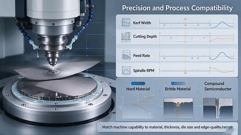
When a dicing street narrows to 30 or 40 μm, the blade has very little room for error. A positioning deviation of one or two microns is enough to nick metallization or cause chipping along the die edge.
Three axis parameters matter most: control resolution, repeatability, and cumulative accuracy. The ADT 8030's Y-axis is specified at 0.1 μm control resolution, 1.0 μm index accuracy, and 1.5 μm cumulative accuracy. The DFD6363 lists Y-axis index positioning accuracy of 0.002/310 mm with a single error of 0.002/5 mm, and a Z-axis movement resolution of 0.0000002 mm with 0.001 mm repeatability. These figures only become meaningful when compared against the narrowest street on your device. If cumulative error approaches the street width, the process is not capable, regardless of how good the blade is. This is the kind of gap that separates a capable dicing saw from one that merely meets spec on paper.
The X-axis drive type influences how smoothly the table travels. Air bearings give very smooth motion and stable velocity at high feed rates, which suits high-speed cutting. Ball screws offer rigidity and are easier to maintain in environments where air supply quality is inconsistent. Neither is universally better; the decision should reflect your speed targets and your maintenance resources.
Vision alignment is where changeover time is won or lost. Continuous zoom magnification in the 70× to 290× range, combined with both vertical and oblique LED illumination, determines how reliably the tool finds low-contrast alignment marks. Automatic kerf inspection adds a layer of traceability by confirming that the cut landed where it was supposed to. If your devices carry faint or unusual alignment features, insist on a live demonstration rather than a datasheet claim.
Automation and Material Handling in Automatic Dicing Saws
"Automatic" means different things on different machines. Some tools automate only the cutting feed and still require an operator to load and unload every wafer. Others run untouched from cassette to cassette, including cleaning and drying.
A fully automatic dicing saw typically strings together a pick-up gripper, a pre-alignment stage, upper and lower transfer arms, a cleaning station, and a drying unit. On the DFD6363, the sequence runs from cassette to pre-alignment, to the worktable, through cutting, then to cleaning and drying before the gripper returns the workpiece. The cycle time of that loop — not the spindle speed — often sets the real throughput ceiling. A dual-spindle machine can cut twice as fast and still deliver no net gain if the handler cannot feed it fast enough. Throughput expectations built on spindle speed alone tend to get reset after the first week of production data.
Material handling compatibility is another quiet constraint. If your line moves wafers in metal frames rather than standard cassettes, the dicing saw must support that mode or you will be adding a transfer step that erodes the automation benefit.
Automatic blade change systems earn their keep in high-mix environments. When a line runs several blade specifications per shift, automated blade wear detection and replacement removes a common source of human error and shortens changeover. For lines with frequent recipe changes, the payback can arrive sooner than expected.
Blade and Consumable Costs in Dicing Saw Operation
Blade costs rarely appear in the capital request, yet they accumulate relentlessly through the life of the tool. Customers tend to discover this line item after installation rather than before, which is why a standing inventory of dicing blades and related consumables matters more than it might seem at the procurement stage.
The range of blade outer diameters and hub types a dicing saw accepts determines how many suppliers you can buy from. ADT's 80WT handles Hub and Hubless blades up to 3 inches in outer diameter, while the 7234 accepts 4-inch and 5-inch annular blades. A wider compatibility window translates directly into procurement leverage and protection against single-source pricing.
Blade wear prediction, available on some platforms, trims height-measurement time and lifts effective throughput. Broken blade detection is a baseline safety feature, but on high-value work such as compound semiconductor or MEMS devices, real-time blade condition monitoring is what prevents a single broken blade from destroying an entire lot.
Hard materials rewrite the consumable calculus. Blade life on silicon carbide, sapphire, or ceramic can be a fraction of what silicon allows. In that situation, a dicing saw built for larger, thicker blades and higher spindle power carries a higher sticker price but may deliver a lower cost per cut, because large-diameter blades hold linear speed and dissipate heat more effectively. Customers cutting third-generation compound semiconductors often optimize for machine price first and rebuild their cost model around blade consumption later.
Choosing a Dicing Saw for Silicon, SiC, and Glass
No dicing saw excels at everything. The material mix on your line should drive the specification.
Silicon remains the most forgiving common substrate, and blade cutting is still the mainstream approach. Silicon carbide changes the equation: its hardness on the Mohs scale is more than double that of silicon, and it demands different blade bonds, higher torque, and more aggressive coolant delivery. ADT's 8020 lists SiC, MEMS, SAW devices, glass wafers, and QFN/LED packages among its target applications. If your line runs both silicon and SiC, configure the spindle and cooling system for the SiC requirement and accept that silicon will simply run comfortably within it.
Laser cutting has moved from curiosity to production reality in specific niches. Samsung has adopted femtosecond laser dicing in its HBM4 process, where ultra-short pulses limit thermal damage and particle generation. But laser absorption varies widely across silicon, SiC, and gallium nitride, so each material needs its own parameter set. Treat laser capability as a complement to mechanical dicing rather than a replacement.
Glass and other brittle materials bring chipping control to the forefront. ADT's 8030 names thin glass as a primary application. Blade selection, coolant chemistry, and feed rate all shift when moving from silicon to glass, and the software's ability to store and switch process recipes quickly becomes a practical asset. The R&D focus on SiC and GaN back-end processes grew out of exactly this realization — that third-generation compound semiconductors behave nothing like silicon and cannot be treated as a variation on it.
| Material | Primary challenge | Configuration priority |
|---|---|---|
| Silicon | Chipping, thin-wafer handling | Gentle handling, precise alignment |
| Silicon carbide | Hardness, rapid blade wear | High-torque spindle, large blades |
| Glass | Edge chipping, micro-cracks | Dedicated blades, matched coolant |
| Ceramic substrate | Brittleness, thermal effects | Low-damage parameters |
| Compound semiconductor | High value, material sensitivity | Real-time monitoring, breakage detection |
| Metal substrate | Burrs, thermal distortion | Cooling capacity, feed optimization |
SECS/GEM and Data Integration for Dicing Equipment
A dicing saw that cannot talk to the factory system is an island, and islands create manual work.
SECS/GEM readiness is the baseline for connecting to an MES. ADT's 8030 and 80WT are both listed as SECS/GEM platform ready. Without it, remote monitoring, recipe management, and automated data collection are off the table, which is a serious gap in a highly automated packaging line.
Process data recording goes a step further. Capturing blade height, feed speed, spindle current, and alignment results creates the traceability needed to investigate yield excursions. Automatic kerf inspection and statistical analysis shorten the path from "yield dropped" to "here is the dicing parameter that drifted."
Interface design affects daily labor. A 19-inch touchscreen with multi-language support and a graphical layout reduces training time and misoperation across shifts. Remote screen-mirroring diagnostics over a two-hour response window only works when the interface exposes the data needed to diagnose a problem without sending an engineer to site.
Dicing Saw Total Cost of Ownership: What to Calculate
The purchase order is the beginning of the spending, not the end.
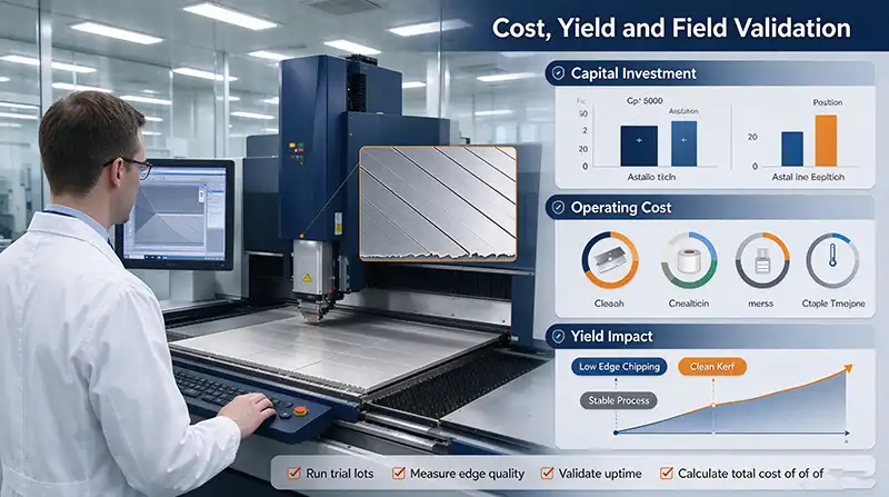
Maintenance access matters more than it appears on a floor plan. Centralized service points that can all be reached from the front of the machine shorten planned downtime. The DFD6560 cuts its footprint by 16% through a shorter spindle and revised frame, and reduces the space needed between adjacent units by 20%. In a cleanroom, that space has a rent, and the savings compound across a multi-tool installation.
Capacity calculations should use real cycle data, not peak speed. Alignment, handling, blade changes, and cleaning all consume time. Ask for measured throughput on a workpiece similar to yours, not a theoretical maximum.
Service coverage can outweigh a specification advantage. When a dicing saw goes down at two in the morning, the distance to the nearest qualified engineer and the availability of spare parts matter more than a marginally better accuracy figure. That is the standard worth applying when you evaluate any supplier's support commitments.
Future-Proofing Your Dicing Saw Investment
Most dicing saws serve three to five years, sometimes longer, and the product mix rarely stands still.
Hybrid process flows are becoming common. Dicing Before Grinding and similar sequences require the dicing tool and the thinning equipment to share a coherent process window. If advanced packaging or ultra-thin wafers are on your roadmap, confirm compatibility before committing.
Larger substrates continue to spread into power and specialty applications. Whether a dicing saw can accommodate workpieces beyond 300 mm, or offers an upgradeable chuck, determines whether it stays useful or becomes a bottleneck.
Consider how actively the supplier develops the platform. Semiconductor equipment evolves faster than general machining hardware. A supplier that keeps investing in software, process recipes, and consumable development keeps your tool current; one that does not leaves you with an orphan within a few years.
Frequently Asked Questions
Should I choose a mechanical dicing saw or a laser cutting system?
They solve different problems. Mechanical blade cutting remains cost-effective for silicon wafers and conventional packaging substrates in volume production. Laser cutting earns its place with ultra-thin wafers below 100 μm, complex geometries, and materials sensitive to mechanical stress.
Does a dual-spindle dicing saw always produce more than a single-spindle machine?
No. Dual spindles accelerate only the cutting step. If alignment, loading, cleaning, or drying cannot keep up, the second spindle adds little. Evaluate the cycle time of the whole dicing saw, not the spindle count.
What should I look for in a dicing saw for silicon carbide?
SiC is roughly twice as hard as silicon on the Mohs scale, so prioritize spindle torque, blade bond selection, and coolant delivery. A spindle above 2.2 kW and support for 4- to 5-inch blades are reasonable starting points.
How do I estimate real throughput before buying a dicing saw?
Real throughput equals effective cutting time divided by total cycle time, multiplied by the achievable feed rate. Total cycle time includes alignment, transfer, blade changes, and cleaning. Request measured cycle times on a workpiece comparable to yours.
Is SECS/GEM really necessary on a dicing saw?
If your factory runs an MES or you plan automated data collection and traceability, yes. Without SECS/GEM, recipe management, remote monitoring, and production reporting all require manual effort.
Why does blade compatibility matter so much?
It determines how many blade suppliers you can use and how much leverage you have on price. A dicing saw that accepts multiple outer diameters and both Hub and Hubless types keeps your consumable options open.
How much should footprint influence the decision?
In a cleanroom, floor space carries a real cost. A dicing saw that saves 16% of its footprint and 20% of adjacent maintenance space produces meaningful savings when several units are installed.
How can I verify cutting quality on my actual material?
Ask for a sample cut. Run your real workpieces under your process requirements on the candidate dicing saw, then measure chipping, street quality, blade wear rate, and throughput.
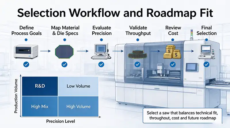
Choosing a dicing saw is an exercise in matching constraints. No machine leads in every category, but the right one is stable on your core application, flexible enough for the next product, and predictable in what it costs to own. Screen candidates in two passes: first eliminate anything that cannot meet the basic envelope, material, or precision requirements, then score the survivors on automation, consumable economics, service reach, and roadmap fit. Wherever possible, let a sample cut — not a specification sheet — make the final case.
The GEEKVALUE application engineering team has delivered more than 200 back-end equipment sets and holds 8 registered core patents, working from a 2,000-square-meter ISO 14644-1 Class 10 cleanroom in Shenzhen. For help applying this framework to your line. Talk to us or browse our semiconductor equipment catalog.