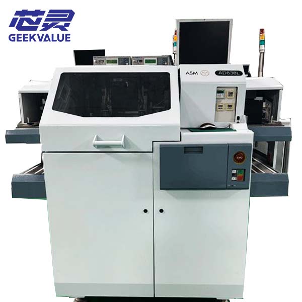
ASMPT MS90 is a front-end wafer sorting system that uses wafer-map data from upstream testing to pick, reclassify and sort dies into designated output positions. It reads sorting files, aligns the wafer and routes each die according to its assigned grade. Unlike die bonders or packaging equipment, its primary function is wafer-level die sorting.
The system supports die sizes from 0.15 × 0.15 mm to 5 × 5 mm. The pickup area reaches Ø150 mm with bottom vision enabled, or 125 × 125 mm without it. For 8-inch wafers, half-wafer table mode extends the pickup area. A 25 × 8 output matrix supports up to 200 grades, with 150 grades in the standard configuration.
Placement accuracy is ±38 µm in the standard configuration and ±10 µm with optional bottom vision. Bottom vision improves alignment when front-side electrodes or patterns interfere with top-down recognition, but adds a die-level inspection step that can reduce throughput. Where standard accuracy is sufficient, the basic configuration may offer faster cycle times.
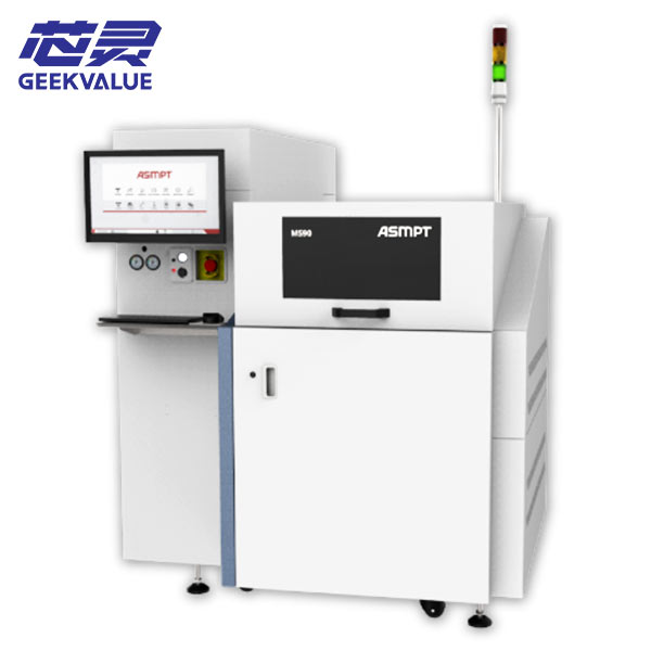
Key Specifications
| Parameter | Specification |
|---|---|
| Equipment Type | Front-of-line wafer map sorting system |
| Die Size Range | 0.15 mm × 0.15 mm – 5 mm × 5 mm |
| Pick Range (Bottom Vision On) | Up to Ø 150 mm |
| Pick Range (Bottom Vision Off) | 125 mm × 125 mm |
| Large Wafer Handling | Up to 8-inch diameter (half-wafer table mode) |
| XY Placement Accuracy (Standard) | ± 38 µm |
| XY Placement Accuracy (Bottom Vision) | ± 10 µm |
| Bin Classification Capacity | Up to 200 grades (25 × 8 output matrix); standard up to 150 |
| Motion Architecture | Dual-head bond arm; direct-drive and linear motors |
| Wafer Size | 2–6 inches standard; 8-inch support via half-wafer table |
| Traceability | 1D and 2D barcode scanning |
| Setup Feature | Electric XY ejector system |
| Footprint (W × D × H) | 1,420 mm × 1,420 mm × 2,045 mm |
Configuration & Procurement Notes
The MS90 is a configurable platform, and two units under the same model name can carry different vision options, output matrices, and software licenses. If you are evaluating a used unit, these are the items that determine whether it will run your product:
Vision configuration. Confirm whether the unit ships with bottom vision enabled. The difference between ±38 µm and ±10 µm placement accuracy is a hardware and software configuration, not a field upgrade.
Output matrix. Verify the installed output box count. A 25 × 8 matrix supports 200 grades; a smaller matrix limits the number of products that can complete in a single sorting pass.
Wafer table mode. If you process 8-inch wafers, confirm the half-wafer table mode is installed and functional.
Pickup tooling. Check the nozzle and needle sets included. Tooling is die-size-dependent — a setup for 0.15 mm dies is not interchangeable with one for 5 mm dies.
Software version and map file compatibility. Verify that the installed software can read the map file format generated by your upstream test equipment.
Motion system service history. Direct-drive and linear motor systems have long service intervals, but request maintenance records for the bond arm and XY stages if available.
Barcode scanning. Confirm the 1D/2D scanner is present and calibrated if lot traceability is required in your process.
Content reviewed by Ms. Li, semiconductor equipment engineer with 10 years in back-end assembly and test.