Matching Coils & Conductors
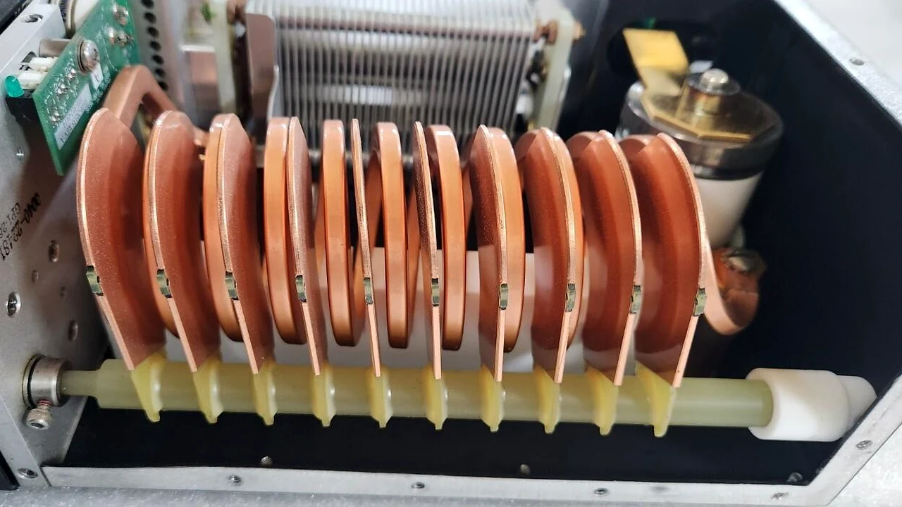
Focus: RF coils, conductors, and RF-path connections. Assessed for physical damage, unstable connections, or thermal degradation.
Semiconductor RF Matching Systems
Repair support for auto-tune stalls, capacitor movement faults and matching that will not settle.
We trace the fault across matching circuit, capacitor actuation, motor-drive and feedback logic before defining a repair scope. Repair is performed only where the capacitor body and RF path remain serviceable, with post-repair impedance verification on a dedicated platform where the model and fixture permit.
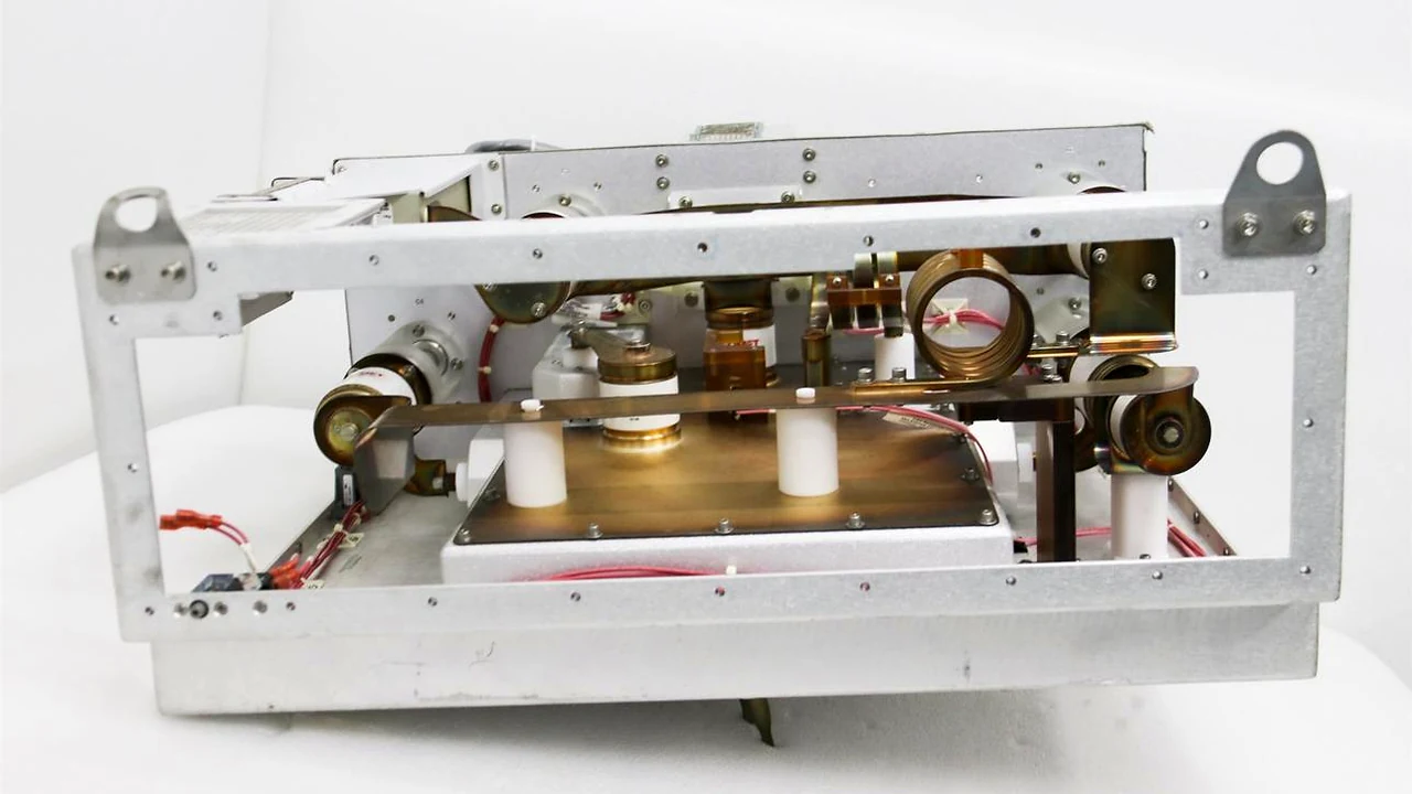 Semiconductor RF matcher
01 / Repair coverage
Our confirmed scope covers electrical, control, mechanical-drive and capacitor assemblies. The repair scope is selected against the unit design, revision and specific fault evidence.
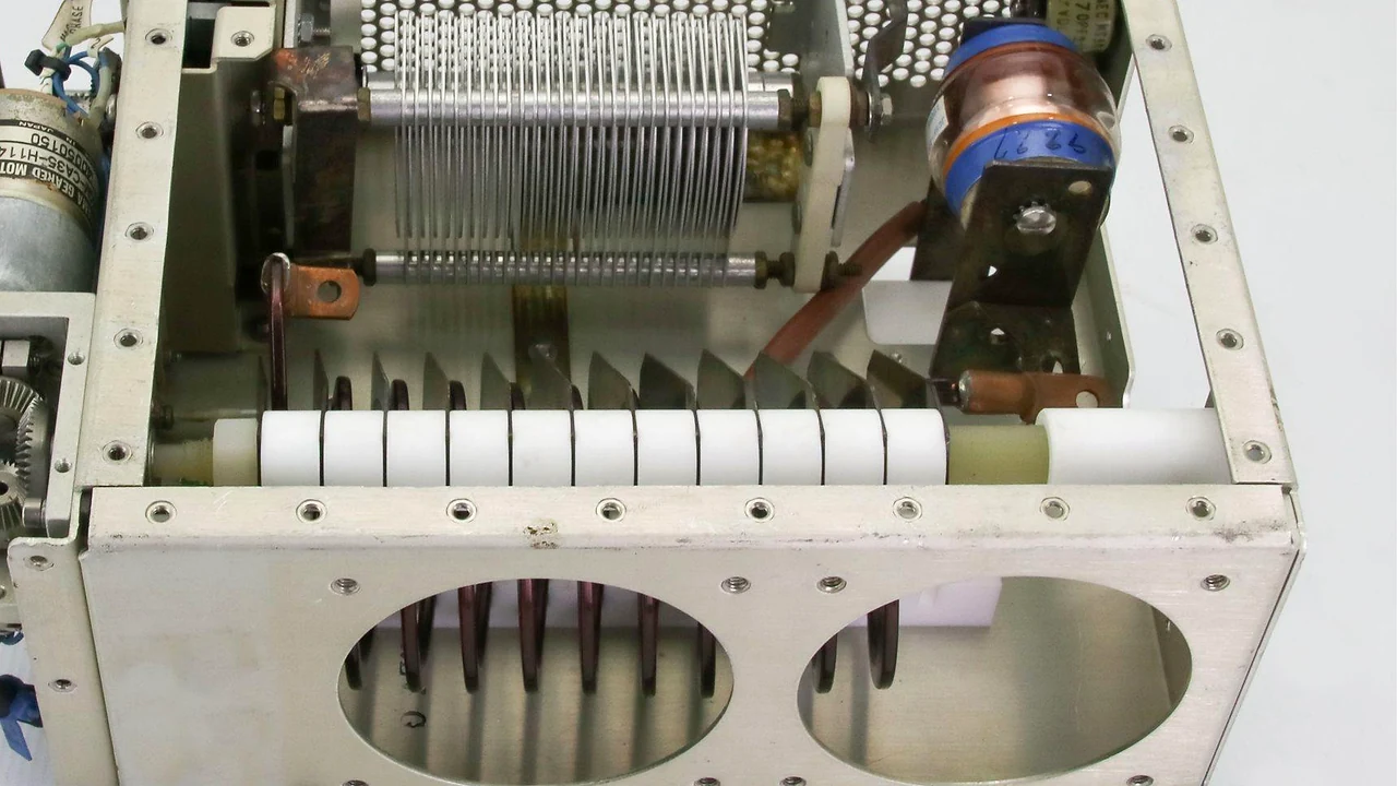
Focus: RF coils, conductors, and RF-path connections. Assessed for physical damage, unstable connections, or thermal degradation.
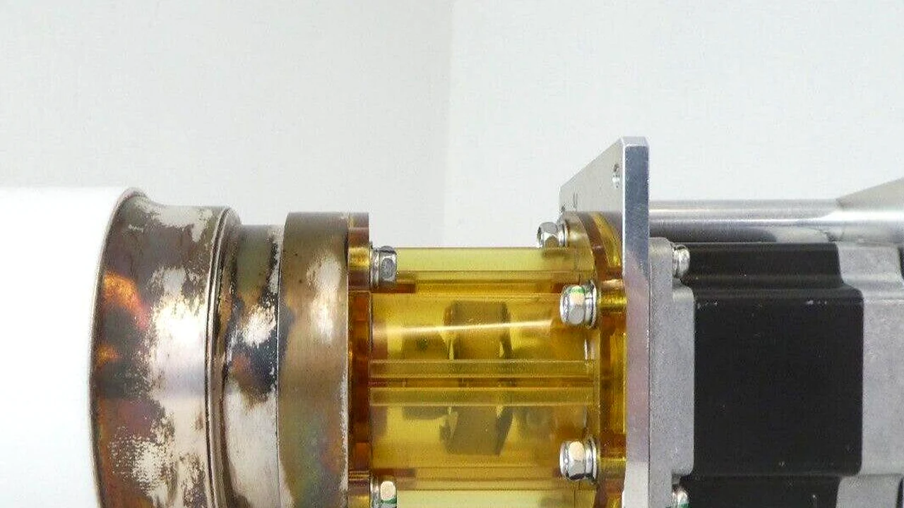
Focus: Tune and Load capacitor assemblies. Covers actuation interfaces, vacuum seal integrity, and movement faults preventing the network from reaching a match position.
Focus: Motor-drive assemblies, couplings, gear trains, and travel mechanisms. Diagnosed for lost motion, restricted movement, or inconsistent positioning.
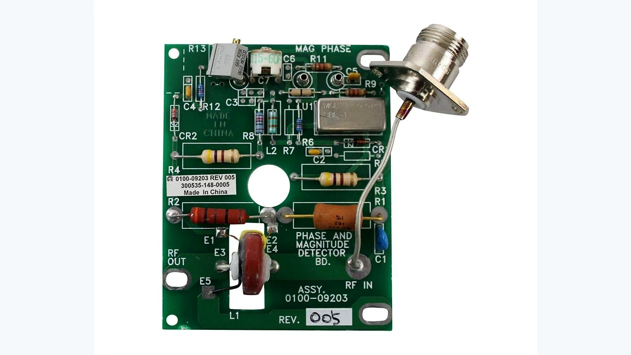
Focus: Control boards, phase/magnitude detection circuits, and position-feedback signals. Targets automatic tuning failures and closed-loop instability.
02 / Fault patterns we address
The same symptom can originate in different parts of a matching system. We trace the RF, drive and feedback paths before assigning the repair scope.
Symptom: Tuning sequence stalls or cannot settle. Focus: Trace control command, phase/magnitude board, motor response, and capacitor position feedback.
Symptom: Commanded and reported positions disagree. Focus: Motor coupling, gear path, capacitor travel, and position sensor (encoder/potentiometer).
Symptom: Continuous adjustment or changing reflected power. Focus: Matcher behavior vs. generator output, RF cables, and chamber load conditions.
Symptom: Inconsistent movement or matching across cycles. Focus: Electrical connections, drive control, and detector signal integrity.
Diagnostic Boundary: A reflected-power symptom does not identify the failed unit by itself. If evidence points to the RF source, see our RF Power Supply Repair service.
Repair Boundary: Vacuum variable capacitors with internal contamination or metal-particle deposition that compromises withstand voltage are recommended for replacement. Actuation and drive faults are assessed for component-level restoration where the capacitor body remains intact.
03 / Why this repair capability matters
Matching network repair needs coordinated work across the RF circuit, capacitor movement and control loop. Our service covers electrical, control, mechanical-drive and capacitor repairs, supported by a dedicated test platform.
We assess the matching circuit, capacitor actuation and drive path together rather than treating the control board, motor and capacitor as unrelated parts.
A dedicated platform supports post-repair closed-loop matching and impedance verification for compatible units. Test setups are scaled to the specific model and fixture constraints.
04 / From fault to return
We operate a structured workflow based on the unit's design and failure evidence. RF, motion and feedback paths are reviewed separately before the confirmed repair and verification route is set.
Confirm manufacturer, model, part number, revision, tool configuration and reported fault behavior.
Review the matching circuit, detector path, motor-drive response, capacitor travel and position feedback.
Complete the agreed electrical, control, capacitor or mechanical-drive repair based on confirmed findings.
Verify closed-loop tuning convergence, reflected-power floor and capacitor position tracking on the dedicated platform. Bench verification does not replace on-tool process qualification.
05 / Typical fault situations
These representative situations show how a repair focus is selected. Actual diagnosis follows the individual unit, its control architecture and connected RF system.
Reported Symptoms: A match command starts but tuning does not settle.
Diagnostic Split: Trace control command, phase/magnitude detection signal, motor-driver response, and capacitor position feedback.
Repair Route: Repair the confirmed electrical or control board fault, followed by closed-loop impedance tuning verification.
Reported Symptoms: Drive movement and reported position disagree.
Diagnostic Split: Check the motor coupling, gear path, physical travel mechanism, and the position sensor (encoder/potentiometer).
Repair Route: Mechanical drive rebuild, capacitor replacement, or sensor recalibration based on physical inspection.
Questions before shipment
Answers for repair scope, component faults, model support and post-repair verification.
Our service scope covers RF matching circuits and coils, vacuum variable capacitor assemblies, motor and mechanical-drive systems, control electronics, phase/magnitude detection where fitted, and position-feedback circuits. The exact work depends on the unit design and diagnosis.
Vacuum variable capacitor assemblies are included in the repair scope. Assessment considers the capacitor body condition, vacuum seal integrity, actuation interface, and movement behavior before the repair route is agreed.
Yes. Motor and mechanical-drive repairs can include the applicable motor, driver, coupling, gear train and movement mechanism. The exact components are confirmed against the matcher architecture.
Possible fault paths include the control command, phase/magnitude detection where fitted, motor-driver response, capacitor movement and position feedback. A single symptom does not identify one failed component.
Control and detection electronics are within the confirmed electrical repair scope. The applicable detector circuit and interface are checked against the specific Matching Network design.
No. Reflected-power behavior can also be affected by RF generator output, cables and connectors, chamber condition and process load. The connected RF path should be considered before assigning the fault to the matcher.
Support depends on model, revision and interface compatibility. Send the nameplate and part number so compatibility can be confirmed before the unit is sent in.
A dedicated Matching Network test platform is available. Functional checks including closed-loop tuning convergence and reflected-power floor are selected according to the exact model and fixture compatibility. Bench verification does not replace process qualification on the installed chamber.
RF matching network and matching box repair
Share the manufacturer, model, part number, revision, tool model, alarm history and clear photos of the unit and connectors. We can review model support, the repair scope and the applicable verification route.